Booting Up the Machine
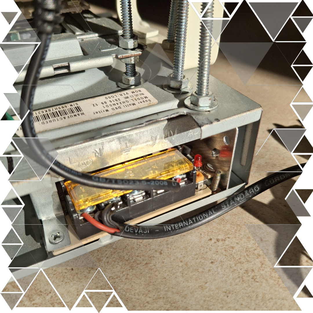
The first step in bringing PCB F.O.R.G.E. to life is getting it powered up — and yeah, it’s a bit like suiting up for a mission. We connect the 230V AC input to the SMPS, which steps it down to a stable 12V 5A supply for the motors and heating element. At the same time, the Raspberry Pi Zero W gets its juice from a 5V adapter — small but mighty, just like the Pi itself.
But here’s where the real magic starts: the moment the Pi boots up, it automatically launches app.py. We set this up by adding a line to the rc.local file, making sure the web interface is always ready the moment power flows. It’s like having JARVIS waiting for commands as soon as you enter the lab.
Once it’s up and running, we head over to the dashboard — a sleek web app hosted right on the Pi using Flask. From here, the control panel gives us three solid options:
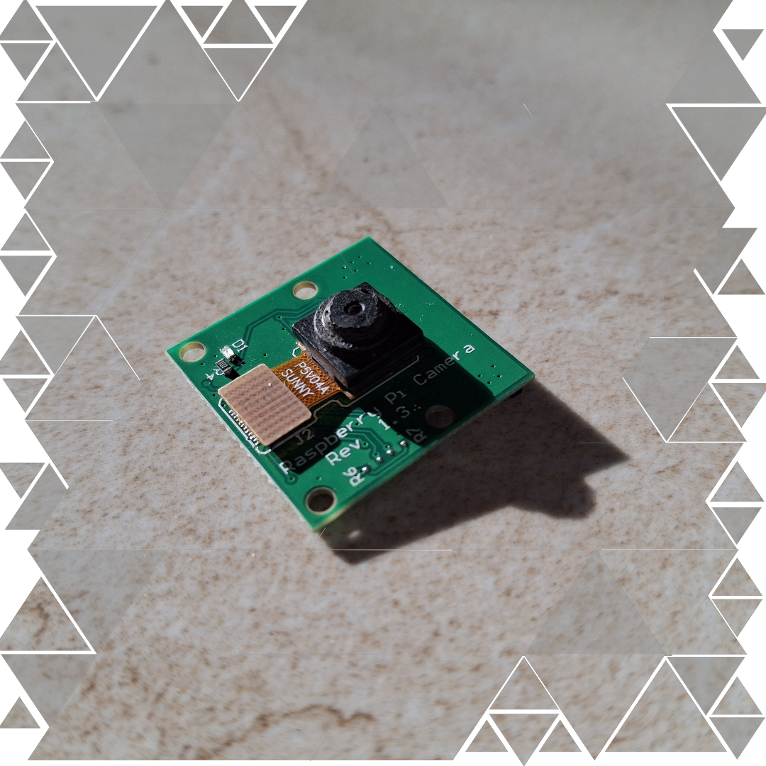
• Capture Image: Snap a real-life PCB image for solder pad detection.
• Upload Image: Use a softcopy PCB design from EagleCAD or similar software.
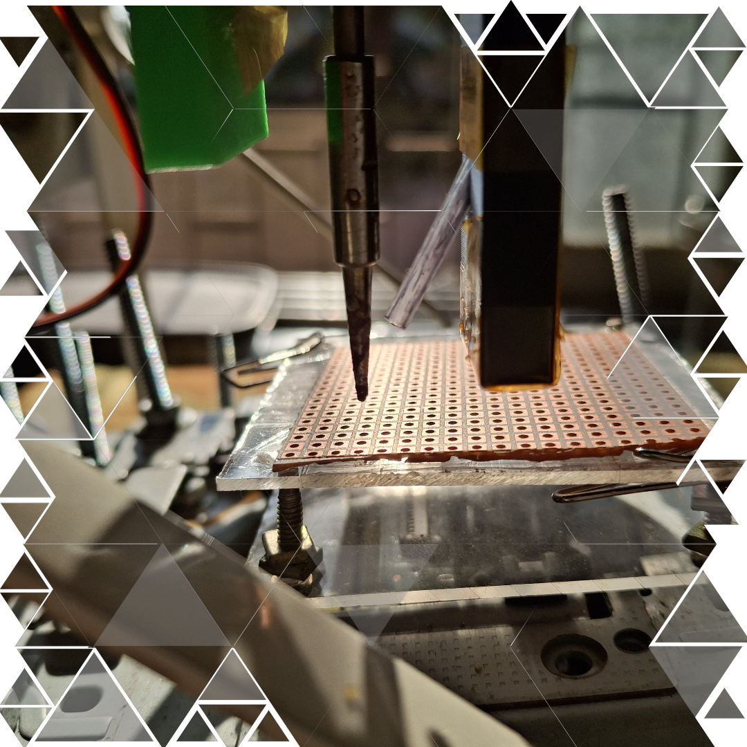
• Initiate Soldering: Once the coordinates are set, start the magic and watch the machine get to work.