PCB F.O.R.G.E.

For Opportunities Reviving Great Era

GitHub LinkedIn Gmail

ASSEMBLY

Background Image 1

Gathering the Scraps

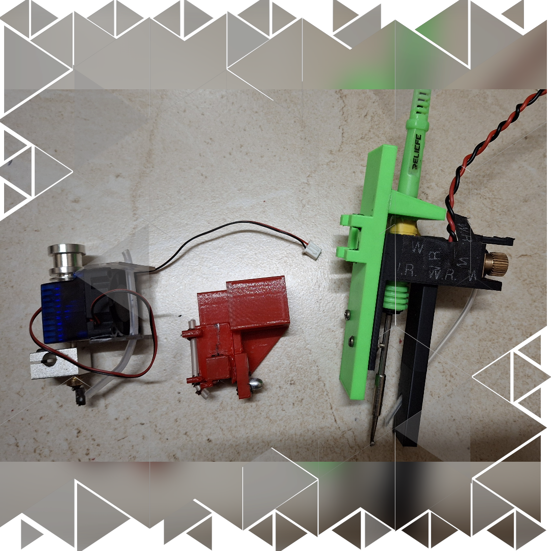
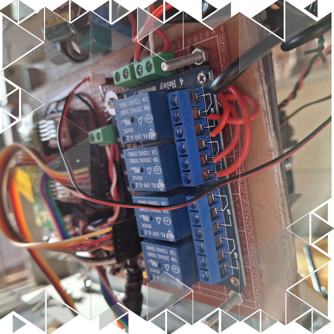
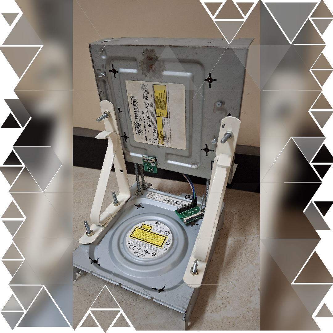
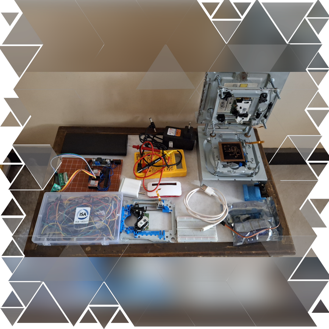
When we started putting PCB F.O.R.G.E. together, we knew every part had to pull its weight. With a limited budget and big ambitions, we got creative. We repurposed DVD stepper motors from old Samsung and LG drives — small but precise enough for our CNC needs. The A4988 drivers gave us the control we needed, while the MG90S servo motors handled the delicate soldering movements. To top it off, 5W soldering pen became our heating element, and the Raspberry Pi Zero W became the brains behind it all. Every component was carefully chosen not just for its function, but for how well it fit into our vision — creating a powerful, cost-effective machine without compromising on performance. This wasn’t just assembly; it was about turning scattered pieces into something with purpose.

Background Image 2

Evolution in 3D Printing

Building PCB F.O.R.G.E. wasn’t just about putting together ready-made components — it was about creating parts that didn’t exist yet. And trust me, that meant a lot of trial and error. We started with the V6 extruder directly mounted as the soldering tool, but it didn’t quite work out — the solder wire just wouldn’t melt properly. So we went back to the drawing board and 3D-printed a custom holder for the extruder. It fit well, but then came version two’s unexpected twist: the 48W heater of the V6 extruder melted our printed holder itself. Yeah, that was a bit of a facepalm moment.

But we didn’t give up. For version three, we switched things up and designed a sturdy, heat-resistant mount to hold a 5W soldering pen. And this time, it worked like a charm. We also created custom brackets for the N20 motor driving the solder wire feeder and a precise mechanism for the MG90S servo to control the up-and-down movement. Every 3D-printed part tells a story of patience, failure, and ultimate success — shaping PCB F.O.R.G.E. into the machine it is today.

Background Image 1

Building the Backbone

When it came to the foundation of PCB F.O.R.G.E., we kept it simple, smart, and efficient. The entire X and Y axis? Built from DVD player mechanisms. And here’s the cool part — we didn’t just take out the stepper motor sliders and toss the rest. We used the DVD player’s own metal casing to hold those sliders in place. That meant no need to build a separate structure — everything fit perfectly with almost zero extra effort. It felt like these parts were just waiting to become something bigger.

For the brains of the machine, we went old school and made our own controller board on a zero PCB. No fancy pre-made shields here — we soldered each device, each module, one by one. It took patience (and a bit of burned fingertips), but the final working controller board was worth every second. Plus, making it ourselves kept the cost down without compromising functionality. We kept the setup compact and efficient, mounting the 12V 5A SMPS right below the horizontal axis to save space. Then came the final touch — attaching the 3D-printed solder pen holder and the feeder mechanism. Piece by piece, everything fell into place, and the backbone of PCB F.O.R.G.E. stood strong, ready for action.

Background Image 2

The Roadblocks

Every great build comes with its share of struggles, and PCB F.O.R.G.E. was no different. When we started assembling the X and Y axis — using those DVD player cases as holders — things didn’t go as smoothly as we hoped. The vertical and horizontal axis holders wobbled like crazy, more like a cantilever ready to collapse than a sturdy frame. We knew if we didn’t fix this, precision would go out the window. So we got creative — added some angled brackets, and just like that, the whole structure locked into place, rock solid. But that wasn’t the end of it. The uneven base of the DVD cases made the entire machine unstable — it wobbled and tilted every time it moved. We needed a quick fix, so we elevated the base with rubber legs. Not only did this stabilize the whole setup, but it also gave the machine a nice, balanced stance.

And then there was the nightmare of positioning those tiny components. Fitting the stepper drivers, the relay modules, the controller board — everything had to be in the perfect spot. It took patience, adjustments, and a lot of trial and error. But in the end, every part found its place, and the machine finally stood — stable, balanced, and ready for action.