PCB F.O.R.G.E.

For Opportunities Reviving Great Era

GitHub LinkedIn Gmail

RESULT

Background Image 1

The Gateway of Control

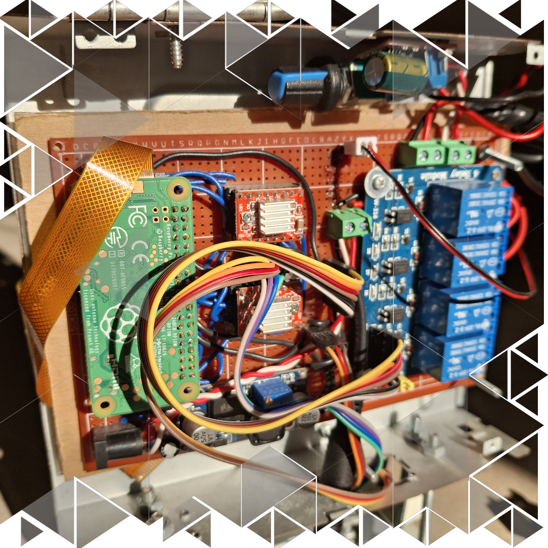
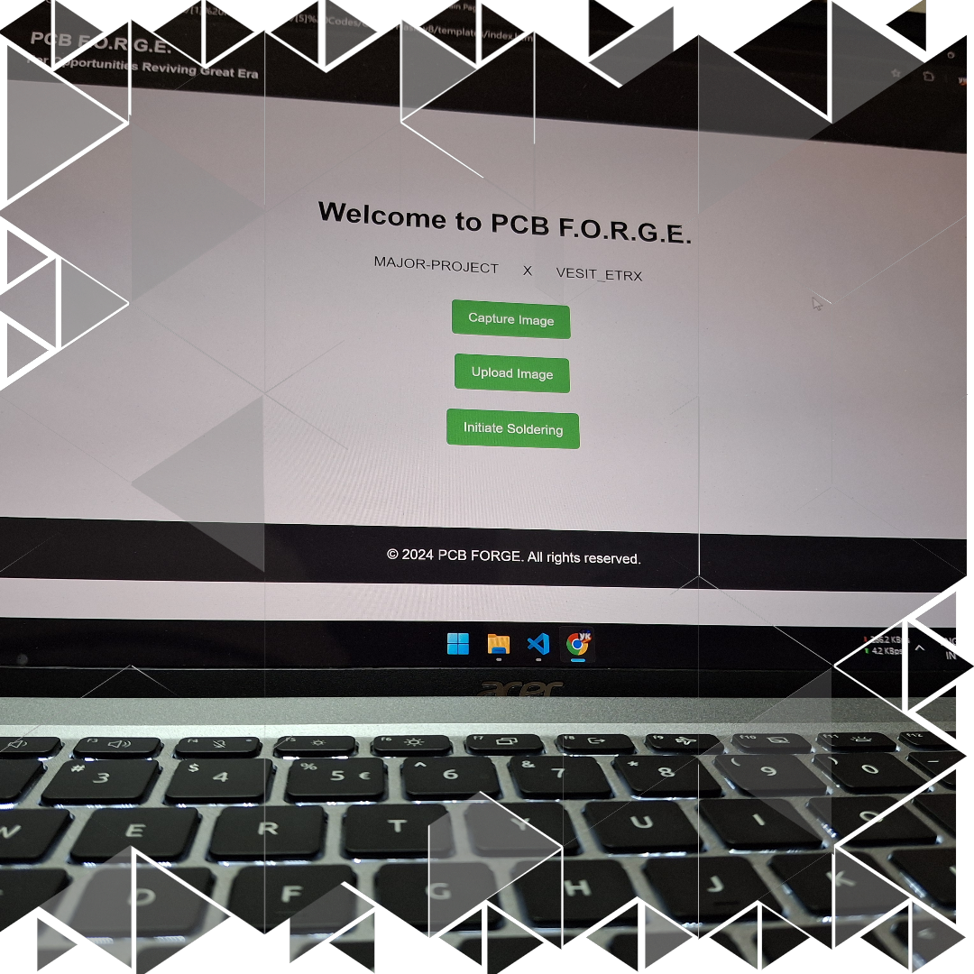
One of the first and most satisfying milestones in this journey was building the dashboard — the perfect bridge between the user and PCB F.O.R.G.E. Hosted on the Raspberry Pi Zero W using Flask, this simple yet powerful interface brought everything together. From capturing real-life PCB images to uploading designs from EagleCAD and finally initiating the soldering process, the dashboard made it all accessible with just a few clicks. But what made this even more special was the fact that everything — and I mean everything — was handled by the Raspberry Pi itself. No external systems, no separate controllers, no additional processing devices. The Pi took care of the camera, image processing, machine control, and the user interface, all in one place. It was like having a compact, self-sufficient powerhouse driving the entire project. Seeing this dashboard come to life felt like the first real proof that our vision was turning into reality.

Background Image 2

Precision in Detection

One of the biggest wins for us was the high accuracy of solder pad detection. When it came to software input — like uploading PCB designs from EagleCAD — the detection worked flawlessly, hitting a perfect 100% accuracy. Every single solder pad was identified without a hitch. But when we moved to real-life PCB images captured by the Pi Cam, things got a little tricky. The custom model we built did an amazing job, but sometimes — and only sometimes — it missed a couple of solder pads. Maybe two or three out of dozens would slip through undetected. And you know what? That’s okay. Considering all the variables like lighting, reflection, and image quality, we were still pretty proud of the accuracy we achieved. This tiny hiccup didn’t take away from the fact that our machine was getting it right almost every single time. And that’s a win in our book.

Background Image 1

CNC Mechanism

When it came to the CNC mechanism, we knew there was no room for compromise. This was the backbone of PCB F.O.R.G.E., responsible for making sure every movement, every soldering point, was right where it needed to be. And honestly? It delivered like a pro. The X and Y axes, built from repurposed DVD player stepper motor sliders, worked with surprising accuracy. The fact that we used the DVD player cases themselves to hold these sliders not only made the entire structure more efficient but also saved us the time and effort of building a separate frame. The result? A compact, sturdy machine that didn’t wobble or shift during operation.

But what really made this system shine was the perfect coordination between hardware and software. Every time the Raspberry Pi sent a command, the stepper motors responded with smooth, precise movements — no jitters, no misalignments. The servo motor handling the up-and-down motion of the soldering pen worked in perfect sync, ensuring the tip made proper contact with the PCB every single time. Even the N20 motor-driven solder wire feeder, with its speed controlled by a PWM module, fed just the right amount of solder at just the right time. This whole setup turned what could’ve been a clumsy process into a beautifully choreographed dance of components — and the results spoke for themselves.

Background Image 2

Soldering: The Moment of Truth

This was where everything we built came together — the machine, the software, the precision — all leading up to this one crucial task: soldering. And let me tell you, seeing that first perfect solder joint was nothing short of magic. Once the coordinates were locked in, the machine followed a beautifully repetitive sequence of actions. The X and Y axes moved in perfect harmony to position the soldering pen right above the target pad. Then came the N20 motor, carefully feeding the solder wire at just the right speed — a speed we could now control thanks to the PWM module (our game-changing addition). This prevented the wire from sliding off the tip and ensured it had enough time to melt properly. As the solder wire touched the heated tip of the 5W soldering pen, a perfect bulge of molten solder formed. That’s when the servo motor kicked in, lowering the entire soldering pen holder so the tip made precise contact with the PCB pad. After holding its position for just the right amount of time — long enough to let the solder create a strong bond, but not too long to damage anything — the servo lifted the pen back up, ready to move to the next pad.

The entire process repeated like clockwork, and despite the complexity of coordinating so many moving parts, the results were incredible. Solder joints were clean, strong, and consistent — exactly what we had envisioned when we first dreamed up PCB F.O.R.G.E.